
Remember me


This study was approved by the Medical Ethics Committee of the Third Affiliated Hospital of the Fourth Military Medical University (IRB-REV-2022193). Prior to participation, written informed consent was obtained from each participant. Each of the three workflows was performed on all patients. The study enrolled 24 individuals aged 18–60 of either gender, each of whom met the following inclusion criteria: complete maxillary and mandibular dentition (excluding third molars), broadly symmetrical maxillofacial development, absence of facial or orbital injuries, normal anatomical appearance of the ear, orderly arrangement of the posterior dental cusps with normal anterior dental overlaps, absence of multi-tooth fillings or extensive prostheses, stable maximal intercuspal position, no history of temporomandibular joint disease or trauma, no history of orthodontic treatment, and healthy periodontal tissue.
The SCI was measured using three distinct workflows, each conducted by the same experienced operator. In the CBCT-IOS workflow, an intraoral scanner (Trios 3; 3Shape, Copenhagen, Denmark) captured both dentitions and interocclusal records in maximum intercuspal position (MIP) and protrusive interocclusal position (PIP), saving the data as standard tessellation language (STL) files. Concurrently, each individual underwent a CBCT scan in MIP, covering both dental arches and the TMJ with a field of view (FOV) of 170 mm × 10 mm, with the scan data saved as Digital Imaging and Communications in Medicine (DICOM) files. Utilizing YAKE software, the arches and bony structures were reconstructed in 3D by adjusting surface thresholds for bone and enamel, and the reconstructed data were saved as STL files. These files, along with the IOS scan in PIP, were then imported into Geomagic Wrap 2021; software (3D Systems, Morrisville, NC, USA). The “pin” function was used to fix the interocclusal record at the PIP position and establish a coordinate system. The “N-point registration” and “best-fit alignment” functions registered the reconstructed STL file, using the exposed anterior teeth of the maxilla as the registration reference area, to obtain the relative position of the constructed STL file at the MIP position, which was named STL file1. The Frankfort Horizontal (FH) plane was determined by locating both external auditory meatus points and one infraorbital point. The patient’s reconstructed STL file was then imported again into Geomagic Wrap, using the same registration functions selecting specific mandibular dentition landmarks as the registration reference area. This step determined the relative position of the skull at the PIP position, named STL file2. STL file1 and STL file2 were then loaded simultaneously to obtain overlapping images of the condyles in two different head positions. Tangential lines were connected to indicate the motion trajectory of the condyle when the mandible moved from MIP to PIP, and linear coordinates were derived. The angle between this line and the FH plane was calculated to obtain the SCI value for each side, and the process was repeated for the other side (Fig. 1).
Fig. 1
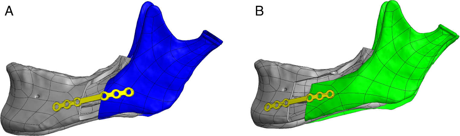
Registration and analysis process using STL files. The reconstructed STL file of the patient underwent registration with the maxillary and mandibular arches at the PIP, utilizing the exposed anterior teeth as the reference area for alignment. This registration was accomplished via “N-point registration” and “best-fit alignment” functions. (a) Reconstructed STL file of the patient’s skull. (b) IOS image of the patient at the PIP. (c) The process of aligning the exposed anterior teeth of the maxillary arch from the patient’s skull (as shown in the reconstructed STL file) with the corresponding maxillary dentition in the IOS. The head position achieved after this registration is designated as STL file1. (d) Re-import of the reconstructed STL file of the patient’s skull for further processing. (e) Registration of the exposed anterior teeth of the mandibular arch of the skull (from the reconstructed STL file) with the mandibular dentition in the IOS. The resulting registered head position from this step is named STL file2. (f) When STL file1 and STL file2 are loaded concurrently, an overlapped image depicting the two distinct head positions is generated, facilitating a comparative analysis of the mandibular and maxillary orientations in these positions
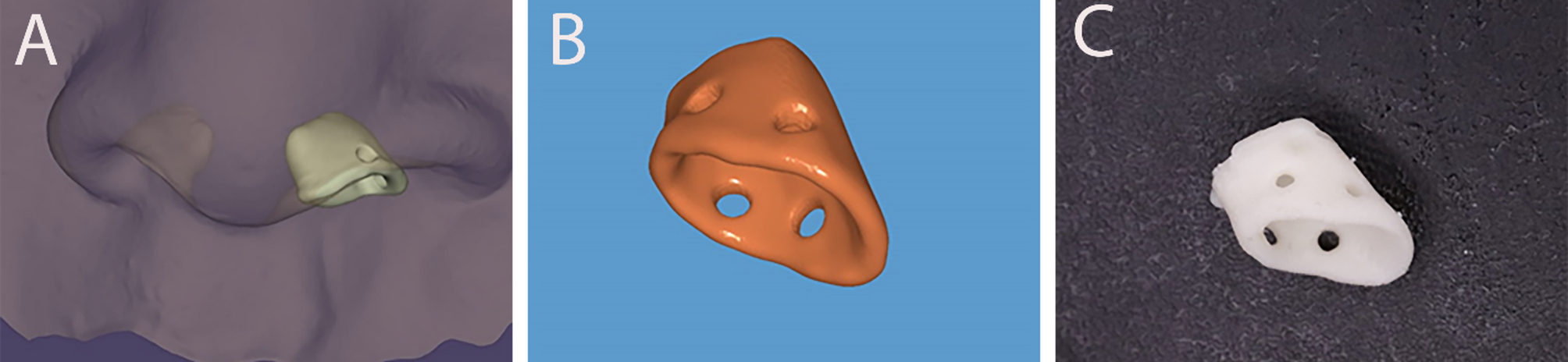
In the FS-IOS workflow, the initial step involved affixing mark points corresponding to the lowest margin of the orbit onto the overlying skin of each participant. This was crucial for the subsequent positioning of the horizontal FH plane. An intraoral scanner (TRIOS 3; 3Shape, Copenhagen, Denmark) was then used to scan the maxillary and mandibular arches and occlusal records at the MIP. The patient was then instructed to perform a protrusive movement with the incisors in edge-to-edge contact, and the PIP was recorded using the intraoral scanner. Subsequently, a facial scanner (3dMDface; 3dMD Inc., Atlanta, GA, USA) captured 3D facial images of each patient in both the closed-mouth position and in MIP, using cheek retractors for exposure. The Object File Format (OBJ) file of the facial scan with cheek retractors and the STL file of the intraoral scan in PIP were imported into Geomagic Wrap 2021 software (Research Triangle Park, NC). The FS of the patient using cheek retractors was registered into the IOS in PIP, employing the “N-point alignment” and “best-fit alignment” functions. The exposed anterior teeth of the maxillary arch served as the registration reference area, with the digital dental cast set as a fixed object. This registered FS file was named OBJ file (1) The OBJ file of the FS in the closed-mouth position was then imported into Geomagic Wrap software, where it was registered into the FS using the cheek retractors. The “N-point alignment” and “best-fit alignment” functions were used again, this time using the skin on the forehead as the registration reference area. The FS using the cheek retractors was set as a fixed object. The superior margin of the meatus externa on both sides of this OBJ file was located, and the FH plane was established together with these two landmarks and the right orbitale (Fig. 2). The OBJ file of the FS including the use of cheek retractors was then re-imported into the Geomagic Wrap software and registered into the IOS in PIP. The “N-point alignment” and “best-fit alignment” functions were used with the exposed anterior teeth of the mandibular arch as the registration reference area, setting the IOS in PIP as a fixed object. This file was named OBJ file (2) Concurrently loading OBJ file 1 and OBJ file 2 represented a superimposition of the two positions, as shown in Fig. 3.
Finally, the posterior margin of the tragus of the left ear and its midpoints were located. Connections between the midpoints and the outer canthus of the eyes in OBJ file 1 and OBJ file 2 were established. The center of the outer tragus was set as the center of a sphere with a diameter of 26 mm to construct the sphere. The intersection point of the sphere and the connecting line from the mid-tragus to the outer canthus of the left eye was identified as the left Beyron point (13 mm anterior to the posterior margin of the tragus of the ear on a line from the center of the tragus to the outer canthus of the eye [16]), indicating the location of the hinge axis. A straight line was established by connecting the Beyron point on the left side of OBJ file 1 and OBJ file 2, and the angle between this line and the FH plane was recorded as the left condylar inclination. The same steps were repeated to obtain the right condylar inclination (Fig. 4).
Fig. 2
Locating the FH plane. (a) FS image of the patient in a closed-mouth position. (b) FS image with cheek retractors in place. (c) Superimposition of the FS image in the closed-mouth position over the FS image using cheek retractors, aiding alignment and comparison. (d) The establishment of the FH plane, using the superior margin of the meatus externa on both sides and the right orbitale as anatomical landmarks
Fig. 3
Registration and superimposition in the FS-IOS workflow. (a) FS image of the patient using a cheek retractor. (b) IOS image of the patient at the PIP. (c) Registration of the exposed anterior teeth of the maxillary arch from the FS with the maxillary dentition in the IOS. The resultant registered head position is designated as OBJ file1. (d) Re-importing the FS image with a cheek retractor for further processing. (e) Registration of the exposed anterior teeth of the mandibular arch from the FS with the mandibular dentition in the IOS. The head position post-registration is named OBJ file2. (f) Overlapping image generated by loading both OBJ file1 and OBJ file2 simultaneously, facilitating comparative analysis of the two different head positions
Fig. 4
Identification and connection of Beyron points in facial scans. Displaying the identification and connection of Beyron points in OBJ file1 and OBJ file2, highlighting their alignment across different head positions
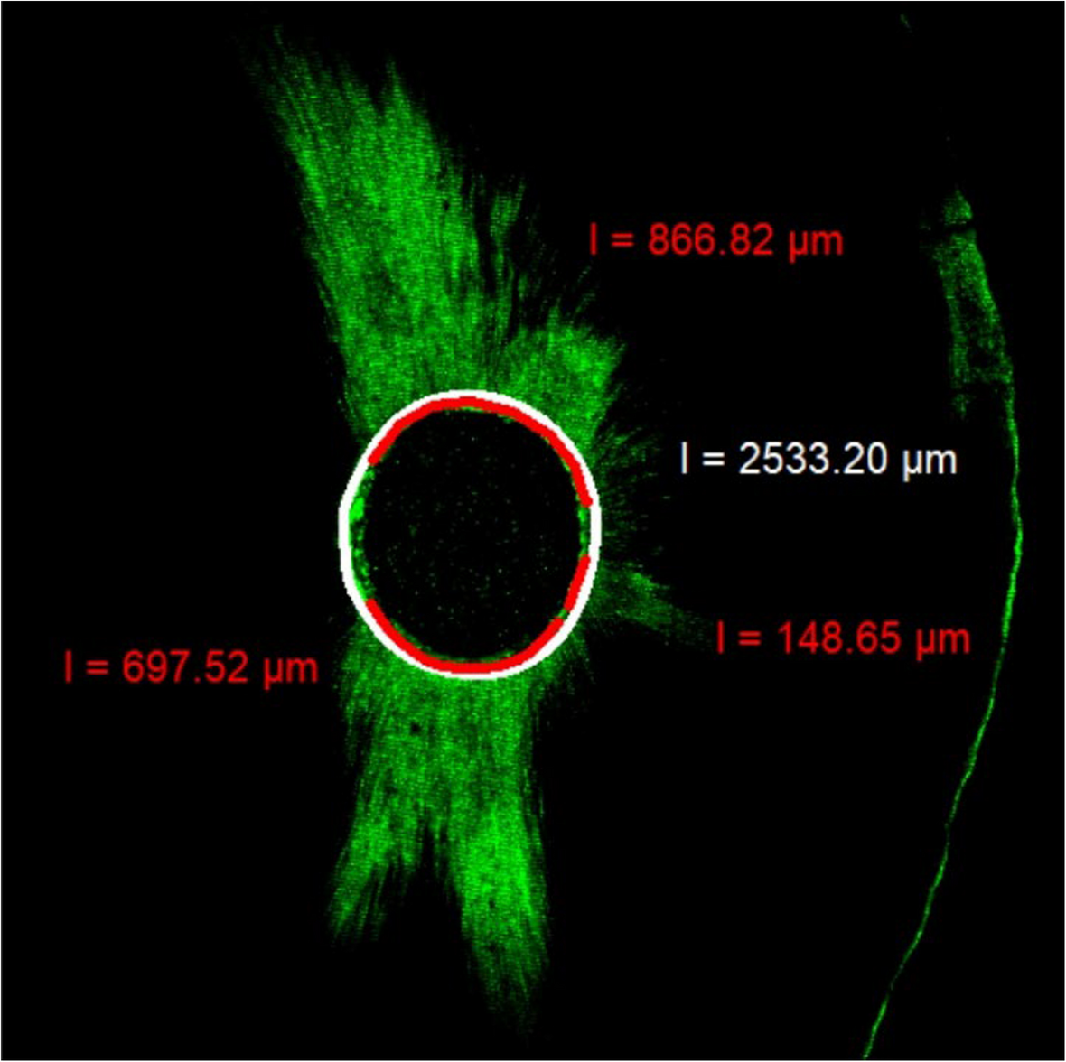
In the JMA workflow, the Jaw Motion Analyzer (Zebris Medical GmBH, Isny, Germany) can be utilized to measure the SCI. The procedure involves affixing a signal receiver to the patient’s head and connecting a signal transmitter to a prefabricated metal mandibular fork. This fork is initially bent to conform to the patient’s mandibular dentition and aligned parallel to the mandibular occlusal plane. Temporary crown resin is applied to the inner surface of the mandibular fork, which, after solidification and trimming, is re-injected with the resin to securely place the fork in the mouth, using the undercut of the teeth for stabilization. Once the material has fully solidified, and it is confirmed that there is no occlusal interference during protrusive and lateral movements, the patient is instructed to perform lateral, protrusive, and mouth-opening movements at a constant speed. Both the start and end positions of each movement are at the MIP. Using the Articulator section of the accompanying WinJaw + software (Zebris), the SCI values in different articulator systems are generated. This process is repeated three times for each patient, with the average of these measurements taken as the final SCI value (Fig. 5).
Fig. 5
Bilateral condyle protrusion track recordings
Statistical analyses were conducted using IBM SPSS Statistics software, v.26 (IBM Corp., Armonk, NY, USA). To assess the normality of the data within each workflow, we used the Shapiro-Wilk normality in conjunction with histogram analysis. The results confirmed that the data distributions confirmed normality, thus the paired-sample T-test was selected to compare the SCI values between the left and right sides in each workflow. To compare the SCI values measured by each pair of workflows, we used the Kruskal-Wallis H test. Finally, the clinical consistency of the three measurement methods was evaluated using Bland-Altman plots (GraphPad Prism 9.5; GraphPad Software Inc., La Jolla, CA, USA) (See Fig. 6).
Fig. 6
Boxplots of SCI values for the three workflows. ns, no significance; * P < .05; SCI, sagittal condylar inclination; CBCT-IOS, cone-beam computed tomography aligned with intraoral scan; FS-IOS, facial scan aligned with intraoral scan; JMA, jaw motion analyzer
Comments (0)