
Remember me


This section describes the hardware and software components and the procedural methods of the presented system, respectively.
Noctopus deviceThe head-mounted frameless stereotactic Noctopus device consists of CT/MRI compatible and biocompatible components (Fig. 1). The determination of the best possible registration marker configuration with a minimum TRE, takes place in three steps.
Fig. 1
Noctopus device main and subcomponents with invasive and non-invasive use cases. (1) Patient base plate with a guide bore for electromagnetic 6-DOF reference frame sensor. (2) Collector (axis centred on the patient base plate) with a left–right slide lock mechanism (orange components). (3) Four marker wheels (blue, green, red and yellow) with corresponding numerals (3a), arms (3b) and marker/sensor holder at the end of each arm (3c) that can carry optical active, passive or electromagnetic sensors in the sensor holders (3d), respectively. (4) Reference frame plate (DRF) with slide lock and four sensor holders for sensors of optical tracking system. The overall device is a lightweight 3D-printable material with size of 55 mm x 35 mm excluding the arms
The placement of the Noctopus device on the head is accomplished preoperatively either using the patient base plate (PBP) by anchoring it to the parietal bone e.g. vertex or bregma with a single self-cutting titanium bone screw (L: 9 mm, \(\) 1.7 mm) (Fig. 1-1a) or using an articulated arm (Fig. 1-5), it is connected non-invasively and without a PBP to a standard Mayfield head clamp (Fig. 1-6). The PBP remains in situ until the surgical procedure is completed. The centred short cylindrical column (Fig. 1-1d) couples the PBP with either collector or DRF plate (optional) components. Coupling and decoupling of those components is realized with a left–right slide lock, which are integrated at the bottom side of collector and DRF plate (Fig. 1-2a and 4a). An electromagnetic 6-DOF sensor (L: 9 mm, \(\) 0.8 mm) can be attached on the PBP through a guide bore for electromagnetic tracking. The indicators (Fig. 1-1b, 2b and 4b) show the mechanical positions of the marker wheels on the collector or DRF plate after coupling with the PBP. Mechanical positioning of all components on the PBP is ensured by a 10 teeth Hirth joint that mesh together on the end faces of each half shaft (Fig. 1-1c). Those radially arranged semi-cylindrical teeth, also on the collector, marker wheels and DRF plate, reliably define the possible mechanical angular positions of the four marker wheel arms.
The collector is coupled with the PBP via a slide lock (Fig. 2a, in opened position) and consists of a stepped cylindrical column (Fig. 2b) that prevents mis-stacking of the marker wheels and contains three axially fixed spherical CT/MRI compatible markers inside (Fig. 2d, transparent view of the column, each marker \(\) 4 mm). All marker 3D positions are detected in the patient image dataset to define the rotation axis of the four marker wheel arms. The indicators (Fig. 2c) show the actual mechanical positioning of marker wheels on the collector. Four color-coded marker wheels (each H: 8 mm, \(\) 35 mm) with their arms, each one having a radiolucent spherical marker at a well-defined position, are stacked on the rotation axis (Fig. 2f, \(\) 4 mm) to be localized in the patient dataset, in the marker/sensor holders (MSH) at the end of an individual arm (Fig. 2e). Each arm is of different length, designed for up to 66 cm head circumference and kept as close as possible to the patient’s anatomy, so that the whole head is covered. They can carry an optical passive reflective sphere, an active infrared LED or an electromagnetic sensor (Fig. 2g,h,i) in its sensor holder (SH). The rotations or mechanical positioning possibilities (registration marker configuration) of an individual marker wheel around the collector are determined by ten numerals (between one and ten steps) using Hirth-toothings and may be varied in steps of 36\(^\).
Fig. 2
Top: Overview of one of the marker wheels with corresponding arm and attachable sensors on the MSH. Bottom: Views of the collector: Left and right show top and frontal views, respectively
When an electromagnetic tracking system is used during the intervention, the DRF plate is rigidly attached on the collector (Fig. 3a, in locked position) only for fixation purpose of the marker wheels. When an optical tracking system is intended, it also carries four optical active or passive sensors on it (Fig. 3 shows three passive, (b) and one active attached sensors, (c)). Depending on the surgery and physical position of the optical tracking system in the operating room, the DRF plate can be designed in a vertically (Fig. 3 left) or in a horizontal/oblique orientation (Fig. 3e right). During patient imaging, all marker wheels are positioned in position 1 (home position) as shown in (Fig. 1). After the registration marker configuration and intraoperative patient registration, but before the surgical navigation, the collector thus also the marker wheels can be decoupled from the PBP and the DRF plate can be coupled with the PBP (Fig. 3f) to allow an unobstructed surgery.
Fig. 3
Top and front view of different DRF plates and its optional coupling with the PBP
Marker detection and localizationA phantom with twelve anatomical targets, realized through implanted titanium bone screws (head \(\) 2 mm) and an attached Noctopus device with marker wheels positioned in home position was scanned in HFS position using a CT scanner at the University Clinic for Radiology in Medical University of Innsbruck. The CT image dataset had a slice thickness of 0.6 mm, with a resolution of 512x512 pixels. It consisted of 504 slices, each with a pixel spacing of 0.488 mm x 0.488 mm. The dataset was loaded into the Noctopus navigation software and visualized as standard DICOM view (Fig. 4), without undergoing any reconstruction or post-processing. The centroids of all registration markers in the MSHs of each particular marker wheel arm and markers in the collector’s column were detected, and their 3D positions in image space were localized automatically based on their geometrical properties using morphological operations [28]. The localized positional coordinates of the markers in the column were used to determine the spatial direction (unit) vector of the rotational axis of marker wheels, while the registration markers in the MSHs serve to generate the 3D candidate registration marker positions around the patient’s head.
Fig. 4
3D centroid positions of the localized three markers in the column and the four registration markers (green) and titanium screw targets (pink) in the patient’s anatomy, shown as axial, sagittal, multiplanar and coronal views. Clockwise from 4th quadrant
Determining the rotational axis and arm positionsTo match mechanical (in the operating room) and virtual (in the imagery) of marker wheel coordinates the 3D rotation axis of the rotatable arms, mechanically identical to the centre of the column, is identified. The axis is found as the line passing through the centroid positions of three collinear markers, in the least squares sense (Fig. 5).
Fig. 5
Stepwise generation of candidate registration markers. (1a) Representation of localized three markers in the column with a calculated 3D direction vector passing through the marker centroids (dashed line with the arrow) and a registration marker (1) in the MSH, while in home position, perpendicular to the vector (1a). (2) Representation of a single virtual rotation (Pos. 2, one step or 36\(^\) in clockwise direction) of a registration marker around the calculated rotational axis with an angle \(\theta \). (3) Representation of possible ten rotational positions (registration marker candidates) of a single registration marker, located in the image dataset in its home position. The virtual positions are identical to the mechanical rotational positions of the marker wheels. The diameter of a rotation (3a, red dashed circle) is determined by the distance between the axis direction vector and 3D marker position in the MSH
Fig. 6
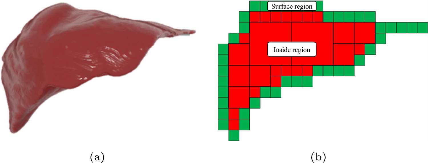
Generated possible candidate registration marker positions (color-coded, depending on the marker wheels) with their rotational axes on the collector. The rotation axis of the arms of the 3D model of the device is positioned on the parietal bone at the calculated rotation axis. Superior and right lateral views of 3D segmented patient dataset, prior to final registration marker configuration selection
Fig. 7
Marker configuration for a desired target (pink sphere) inside the patient’s 3D model, represented from superior and anterior directions. The blue marker wheel is set to the position number 10, while green to 7, red to 3 and yellow to 9 as indicated on the marker wheels by the indicators and additionally shown as enlarged at the left side of the scene. Synthetic radiograms (cranio-caudala, left and frontal, right) with overlay of Noctopus device
Fig. 8
Experimental setup with 3D-printed Noctopus device. a Aurora tracker. b Navigated phantom patient with attached and configured Noctopus device. c Navigated probe placed on one of the target screw head
The possible candidate rotational positions subset \(S_i(x',y',z'), \left| S_i \right| = 10\) of a localized single registration marker (Fig. 6) is generated using the rotation matrix: \(\begin x' \\ y' \\ z' \end=\begin (p(j^2\text k^2)-i(qj\text rk-ix-jy-kz))(1-c)\\ \quad \text xc\text (-rj\text qk-ky\text jz)s \\ (q(i^2\text k^2)-j(pi\text rk-ix-jy-kz))(1-c)\\ \quad \text yc\text (ri-pk\text kx-iz)s \\ (r(i^2\text j^2)-k(pi\text qj-ix-jy-kz))(1-c)\\ \quad \text zc\text (-qi\text pj-jx\text iy)s \end\)
where \((i, j, k) \in \mathbb ^ \) is direction vector of rotational axis, \((p, q, r) \in \mathbb ^ \) is the pivot point of the direction vector passing through the marker centroids in the column, \((x, y, z) \in \mathbb ^ \) is home position of a registration marker in image space, c is cos \(\theta \), and s is sin \(\theta \). \(\theta \) is varied in steps of 36\(^\).
Fig. 9
Partial screenshot of the intraoperative navigation while the accuracy of the registration on a target was qualitatively evaluated by localizing the implanted titanium screws with the navigation probe. The crosshair on DICOM views (axial, sagittal and coronal, from left to right) indicates the actual position of the probe tip placed on the screw head. Small titanium screws are known to hardly produce image reconstruction artefacts in CT imaging [30]; thus, the clarity of the images is not affected
Table 1 Intraoperative targeting accuracy results in mm for various anatomical targets in the cranial space using determined best marker configurationsFig. 10
Determined best marker configurations for each individual target and distance between marker’s centroid (CoM, orange sphere) and target (pink sphere), represented from anterior and superior directions on the patients 3D model. The Noctopus device was removed from the scene, and only corresponding marker positions were left for better visibility. Spherical distribution and not collinear arrangement of the registration markers around the target are noticeably. Additionally, for off-centre targets (1, 2, 7, 8, 9, 10 and 12) a variety of registration markers are positioned near to the target, while one of them at a distance or contralateral, which provides a low, uniform TRE
Determining the best registration marker configurationA brute-force search finds the best configuration on base of all possible candidate positions \(S= \left\,...,S_} \right\} \) from all marker wheel permutations obtained in 2.3. For each permutation step \(S_\), a TRE value \((TRE_)\) is calculated [29] and the fiducial localization error is estimated (\(FLE_\)) from repeated FRE measurements [29] as \(\left\langle FLE_^ \right\rangle =\frac \times \mu \), where N is the number of registration markers and \(\mu \) is the squared average value of measured FREs, preoperatively. This process finds the four marker wheel positions with minimum TRE value, where \(TRE_ =min\begin \begin TRE_ \end i= 1,...,i^} \end\) in the preoperative phase (Fig. 7). This can be also done intraoperatively for a single or multiple anatomical target/s. After rotating the marker wheels to the recommended configuration, the sensors of the selected tracking system are attached into the marker/sensor holders and the sensor positions read out. The patient is registered with the preoperative image dataset automatically using the standard rigid-body registration technique [3].
Noctopus navigation softwareA plugin-based, platform-independent surgical navigation software system featuring marker localization, pre-/intraoperative marker configuration, intraoperative patient registration and navigation was developed. All the required modules were implemented using open-source C++ and Python libraries such as the common toolkit, the visualization toolkit, insight segmentation and registration toolkit, image-guided surgery software toolkit and open network interface for image-guided therapy and runs on a standard computer.
Comments (0)