
Remember me
Advances in decoding algorithms have now made it possible to extract information from brain signals. Relevant information such as motor intentions (Chen et al., 2022; Benabid et al., 2019; Chamanzar et al., 2017; Hammer et al., 2013; Spüler et al., 2014), speech (Shaeri et al., 2024; Metzger et al., 2022; Herff et al., 2019), epileptic seizures (Guirgis et al., 2013; Yoo et al., 2013) and Parkinson tremor state (Shin et al., 2022) can be detected. The information can be used in closed-loop systems such as deep brain stimulation applications for epileptic seizures (Fleming et al., 2023; Kavoosi et al., 2022; Shin et al., 2022; Stanslaski et al., 2012; Sridhara et al., 2011; Chen et al., 2010), and essential tremor (Fraczek et al., 2021; Opri et al., 2020). Some early medical products already exist for these applications (Thenaisie et al., 2021; Jarosiewicz and Morrell, 2021).
In addition, the extracted information can be used in experimental BCI (BCI) applications such as controlling an exoskeleton (Benabid et al., 2019) or generating stimulation patterns for impaired patients after spinal cord injury (Lorach et al., 2023; Younessi Heravi et al., 2023; Greiner et al., 2021). The focus of this work is hardware systems for BCI applications, as these have been less explored although they have significant potential for addressing motor rehabilitation.
Methods for brain signal recording can range from fully-invasive to non-invasive. MEAs (MEAs), implanted directly into the brain tissue, offer a high spatial resolution as they are able to capture single-neuron signals (Musk and Neuralink, 2019; Maynard et al., 1997) while ECoG (ECoG) arrays, placed on the surface of the brain, measure signals averaged over thousands of neurons with limited invasiveness (Matsushita et al., 2018; Mestais et al., 2015). Non-invasive techniques can also be used for brain signal acquisition. EEG (EEG) signals detect electric signals averaged over a larger number of neurons than ECoG (Shokoueinejad et al., 2019) and can be used for brain signal decoding (Wu et al., 2024; Chamanzar et al., 2017; Wang et al., 2016; Sridhara et al., 2011).
Other non-invasive methods include MEG (MEG) and fNIRS (fNIRS). MEG measures magnetic activity in neurons, using machines that are physically large, hence not portable. The fNIRS method is based on detecting changes in hemodynamic activity by measuring variations in oxyhemoglobin and deoxyhemoglobin concentrations. Although fNIRS devices have become more portable, they do not meet the needs for real-time motor assistive applications, as they have a response-time of a few seconds (Ortega-Martinez et al., 2022), much slower than methods based on electrical signals.
General purpose microprocessors have a power consumption that is too high for battery-powered miniaturized medical applications. There is thus a growing need for custom hardware solutions that can decode brain signals using minimal power, while also meeting other well-known metrics such as accuracy and low-latency. The focus of this work is to analyze the state-of-the-art dedicated hardware platforms for BCI and to compare them using a set of metrics that we propose. The remainder of this paper is organized as follows. In Section 2, we present the articles that were included in this analysis. In Section 3, we propose metrics to analyze the performance of decoding circuits, then we compare the identified systems using these metrics. In Section 4, we highlight the most innovative power optimization techniques used in the selected circuits. In Section 5, we discuss the findings of our analysis and conclude with Section 6.
2 Literature review of BCI decoding circuits 2.1 Search methodologyWe performed a review of the literature on hardware systems for brain signal decoding and identified papers presenting hardware systems that could be used for BCI motor decoding. The search was performed using PubMed, Scopus, Web of Science, IEEE Xplore and Google Scholar, and covered published work between 2010 and 2025, a period that witnessed a significant progress in chip development for BCI applications. Search queries were based on boolean combinations of BCI relevant keywords and expressions such as “Brain-computer interface,” “Motor decoding,” “Electroencephalography,"“Electrocorticography,” “Microelectrode Array” with others related to hardware such as “Hardware,” “Circuit,” “Chip,” “Low-power.” The queries were progressively refined to focus the results, and the search constraints were occasionally relaxed to explore a larger scope.
We mainly focused on circuits for BCI motor decoding, excluding systems that are meant to be used exclusively for neuromodulation or detection of epilepsy (Fleming et al., 2023; Tsai et al., 2023; Chua et al., 2022; O'Leary et al., 2018; Bin Altaf et al., 2015; Stanslaski et al., 2012) and tremor (Fraczek et al., 2021; Opri et al., 2020). We also did not include systems that only perform data acquisition (Lee et al., 2023; Reich et al., 2021; Lim et al., 2020; Matsushita et al., 2018; Mestais et al., 2015) or compression (Jang et al., 2023). In addition, although software approaches (Lorach et al., 2023; Chen et al., 2022; Yao et al., 2022; Volkova et al., 2019; Behrenbeck et al., 2019) are interesting for motor decoding, they have been excluded from the study as our aim is to compare BCI hardware systems. In general, circuits designed for SSVEP (SSVEP) decoding, such as Kartsch et al. (2019) have not been considered in the scope of the current study.
Although we focused on motor decoding, some systems with non-motor applications have been included. In fact, some emerging circuit techniques have potential to be used for future BCI motor applications. These exceptions are summarized as follows.
• The circuits presented in Sridhara et al. (2011) and Chen et al. (2010) have only been tested for epileptic seizure detection although they had been initially designed for general medical applications that require on-chip signal processing.
• The system in Shaeri et al. (2024) decodes text characters and is tested on auditory stimuli in mice. It was however included as we believe the innovative approach consisting of using an LDA (LDA) classifier with the DNC (DNC) features could be used for motor decoding.
• In Zhong et al. (2024), the authors describe a circuit that uses SSVEP to control a drone. Although we did not include circuits that exclusively decoded SSVEP, we consider this one an exception, as the decoding was used for a 4-DoF (DoF) control and the chip is one of a few systems that can perform online updates of the decoding model. Such method could be generalized for BCI motor applications.
• The circuit in Malekzadeh-Arasteh et al. (2020) describes an analog approach for feature extraction. Although it does not actually perform decoding, we have included it due its innovative approach. However, we only include it to discuss the power consumption and the optimizations that were applied. Similarly, the Neuralink circuit in Musk and Neuralink (2019) was also included in the power comparison. The systems in Liu et al. (2017) and Zhang et al. (2011) also extract analog features and Liu et al. (2017) implements a closed-loop neurostimulation. The main contributions of these two papers will be highlighted in Section 4.3.1 discussing emerging analog approaches.
2.2 State-of-the-art summaryThe block diagram in Figure 1 shows the main steps that a decoding system implements between the recorded brain signals and the outputs sent to the effector. The decoder takes in N channels, sampled at a given (SR) with a resolution of n bits and it outputs a classification as one of M classes with a (DR). For some decoders, an intermediate feature extraction step is applied before generating the outputs. In such cases, the decoder model can be split into two sub-modules: the feature extractor and the feature decoder. We assume that the features F are extracted at the same rate as the outputs (DR).
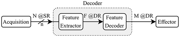
Figure 1. Reference model for a BCI Decoder showing a two-step decoding using feature extraction.
The reviewed works are listed in Table 1 where we show the type of signal that is decoded, the number of channels N, the input (SR), the bit resolution n of the ADC (ADC), the type of features, the extraction method, the number of features F, the type of task, the type of decoder, the number of output classes M, the (DR), the accuracy, the power consumption and the hardware implementation. When input (channel or feature) selection is applied, we report the number of selected inputs followed by the total number.
Table 1. Summary of state-of-the-art brain signal decoding hardware implementations.
For the included circuits, the reported power consumption is that of the whole system, which may perform feature extraction, decoding or both. For the Neuralink circuit (Musk and Neuralink, 2019), we report the acquisition power consumption as it dominates the overall power consumption. Note that, although most of the papers describe systems that are implemented on ASICs (ASICs) or FPGAs (FPGAs), some are based on MCUs (MCUs) and DSPs (DSPs). For instance the approach described in Wang et al. (2019) uses a general purpose MCU to run the decoding algorithm. Furthermore, the system in Wang et al. (2016) is based on a DSP. For ASICs, the choice of process technology node (in nm) will have a major influence on the overall power consumption and fabrication cost, which is why it was included in the table. Although the implementation heterogeneity makes it difficult to establish a completely fair comparison, our objective is to discern broad power and performance trade-offs. To our knowledge, this is the first literature analysis that introduces a set of quantitative metrics to compare a broad range of hardware decoders for motor BCIs.
The system in Shin et al. (2022) has two use cases, one where EEG signals are decoded for seizure and Parkinson disease tremor detection and one where ECoG signals are decoded for finger movement classification. Similarly, two configurations are described in Musk and Neuralink (2019), with different numbers of channels (1,536 and 3,072, respectively). The circuit in An et al. (2022) will also appear twice in the next section's graphs as in was tested for two decoding tasks (1-D and 2-D movement). Although the decoding system in Zhong et al. (2024) is tested for different applications, we only focus on its use in motor imagery.
MEA systems sample at a higher rate in order to detect spikes and they generally do not extract intermediate features, but instead, typically decode temporal characteristics (e.g. firing rate) of the spike train (Shaeri et al., 2024; Tanzarella et al., 2023). However, the MEA decoder in An et al. (2022) extracts SBP (SBP) features, the average of a signal filtered in the 300–1,000 Hz band. For ECoG and EEG, the most common extracted features are EBs (EBs) that measure the signal energy at specific frequency ranges. Common frequency bands for these signals include δ(0–4 Hz), θ(4–8 Hz), α(8–13 Hz), β(13–30 Hz), and γ(30–100 Hz) bands (Tam et al., 2019). ECoG signals can also have a high-γ (75–200 Hz) modulation during movement and speech. One approach to extract time-frequency components is to use a wavelet transform (Grossmann and Morlet, 1984). Another system (Agrawal et al., 2016) directly performs a PCA (PCA) on the raw signals, and uses the obtained components as features for decoding. The number and type of features plays a key role in determining the decoding performance and energy consumption of the overall system.
Many of the existing hardware decoders (mainly for EEG and ECoG signals) presented in Table 1 are limited to two output classes and the decision rate (the number of classifications per second) is often below 5 Hz. Emerging motor control applications require more classes to control a higher number of DoFs, for multi-dimensional movements.
Most of the systems use linear decoders, with many using Bayesian models. The system in Wu et al. (2024) performs a TRCA (TRCA), which is an end-to-end decoding method where the signals are matched with templates tailored to the output classes. The circuit in An et al. (2022) uses a SSKF (SSKF) to decode a 1-D or 2-D motor task. Decision trees are another approach for classification, which was used by Shin et al. (2022). Some of the systems use neural network approaches: Zhong et al. (2024), Ma et al. (2019), Boi et al. (2016) and Chen et al. (2015) directly decode the raw input signals, whereas, Agrawal et al. (2016) uses a MLP (MLP) to decode PCA-based extracted from ECoG signals.
It is important to note that all the systems, in Table 1, that perform decoding, use a model that has been trained offline. Two circuits (Wu et al., 2024; Boi et al., 2016) are however able to update the model coefficients based on error feedback.
From Table 1, it can be seen that the algorithmic approaches for brain signal decoding are highly heterogeneous, suggesting there is not yet a consensus on the best approach. All systems report accuracies that are typically over 80%, although the decoding difficulty varies with the different tasks. The reader will note that there is a huge variance in the reported power consumption, and exploring the trends that impact power consumption is the focus of the following sections.
3 Comparison metrics for BCI system design and evaluationIn the literature on algorithms for brain signal decoding, the primary metric of interest is usually the classification or decoding accuracy. For real-time motor applications, it is also important that the systems achieve a sufficiently high decision rate to meet the latency requirements of the target application. In order to compare different decoding systems, we consider the simplified reference “decoder” model (Figure 1). We define the IDR (IDR) as the total input bits per second in Equation 1.
IDR[bits/s]=N×n[bits]×SR[Hz] (1)Note, for circuits that perform channel selection, N is the number of selected channels.
3.1 Analysis based on output classes per secondControlling a system with a large number of DoFs requires a decoder with more output classes, and of course, achieving high accuracy with a large number of output classes is more difficult. To capture both the task difficulty and the latency requirement, we propose a metric called CpS (CpS), defined in Equation 2.
CpS[classes/s]=M[classes]×DR[Hz] (2)In Figure 2, we present a scatter plot of the systems (log-log scale), where the horizontal axis corresponds to the IDR and the vertical axis corresponds to the output CpS. The shapes correspond to the tested application, the numbers in the shapes refer to the paper references in Table 1, and the colors correspond to the type of signal being decoded.

Figure 2. Output classes per second as a function of the input data rate (bits/s). The numbers represent the references numbers in Table 1.
Despite the systems being highly heterogeneous, we note an increasing tendency for the decoded CpS as function of the IDR. A least-squares fit trendline has been plotted. The regression yields a strong positive correlation (R-value = 0.849 for a Spearman's test with a p-value of 0.000002). The equation for the trendline is given in Equation 3. This trend may be useful to designers of BCI motor systems to estimate the required IDR for decoding a given number of CpS.
CpS=0.097×IDR0.38 (3)The circuits presented in Chen et al. (2015) and Rapoport et al. (2012) are outliers, achieving a high CpS value as they are able to decode a high number of classes (12 and 32) at a high (11.1 and 50 Hz) using highly parallel compute operations.
3.2 Information transfer rate to measure a decoding performanceThe ITR (ITR), described in Pierce (1980), is a metric frequently used in BCI systems to describe the amount of information being extracted, taking into account the number of classes M, the interval between decisions 1/(the maximum time to produce one new classification for real-time applications), and the achieved accuracy P. The formula for computing ITR is shown in Equation 4.
ITR[bits/min]=60×DR×(log2M+Plog2P+(1-P)log2(1-PM-1)) (4)Our hypothesis is that systems are not significantly differentiated by accuracy, but that accuracy is mainly a requirement for the system usability. This suggests that, once the accuracy requirement is met for a given task, a high ITR reflects a high and number of classes M, thus a high CpS. In Figure 3, we present a scatter plot of ITR vs. CpS. It clearly shows that the two metrics are highly correlated (R-value = 0.97 for a Spearman's test with a p-value of 10−11), showing that accuracy has a marginal influence on the ITR of the systems included in this study. In the remainder of this paper, we will consider the ITR as a metric that reflects the CpS value to compare performance, while validating a sufficient level of accuracy that makes a system usable.
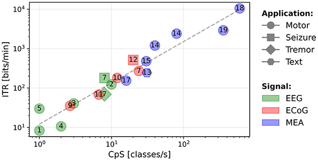
Figure 3. Scatter plot of the ITR (bits/min) as a function of the CpS (classes/s).
3.3 Analysis of circuit power consumptionThe CpS and the ITR metrics depend on the rate at which information is output, but they do not provide insight into the computational complexity required to perform the decoding. Given the diversity of decoding approaches, both in terms of the algorithms and the numeric formats, it is difficult to analytically determine the computational cost of an algorithm, for example by counting the number of arithmetic operations. The power consumption of a decoding circuit thus provides an indirect measurement of the computational cost of the decoding technique.
3.3.1 Power vs. IDRA scatter plot of the power consumption (in mW) of the circuits vs. the IDR is shown in Figure 4. The plot shows that non-motor applications (epileptic seizure and PD (PD) tremor) using EEG and ECoG signals (gray box) consume less power than those decoding motor intentions. This may be due to the smaller number of features, which require fewer compute operations. For example, only the β-band is extracted in Sridhara et al. (2011) and only the high-γ band in Malekzadeh-Arasteh et al. (2020).

Figure 4. Power consumption (mW) as a function of the IDR (bits/s). Non-motor decoding circuits are grouped together (gray), and motor decoding circuits are grouped according to the signal type: green for EEG, red for ECoG, and blue for MEA.
For motor decoding, the circuits can be separated into three groups according to the type of signal. For EEG (green box) and ECoG (red box), the power consumption does not show a strong correlation with the IDR. It implies that the power consumption is determined by the type of processing, including feature extraction, rather than the amount of input data. It is interesting to note that the reported power consumption of the EEG and ECoG decoding circuits is quite similar, while the ECoG circuits decode a much higher IDR. This might be explained by the fact that EEG signals are averaged over a larger number of neurons than ECoG signals (Shokoueinejad et al., 2019), thus requiring more processing to extract relevant information.
In MEA systems, the IDR is significantly higher due to a higher (SR). The plot also shows that the power consumption scales with the IDR for these systems. As MEA systems are often based on spike detection and sorting (Zhang and Constandinou, 2023; Yoon et al., 2021; Toosi et al., 2021; Rapoport et al., 2012), the main variable is the number of inputs or the sampling rate, which determines the IDR. This power dependency could also be due to the MEA signals requiring less computation than ECoG and EEG, which means that the majority of the power is used for data acquisition or transmission, parameters that directly scale with the IDR. As the field evolves, and new circuits appear, it will be seen if this trend continues.
3.3.2 Power per channel vs. ITRThe ITR characterizes the amount of useful information output by the system, considering the DR, number of output classes M, and the decoding accuracy P. As discussed in Section 3.2, the ITR primarily reflects the classification rate, as the accuracy of the studied circuits does not vary significantly. The computational cost of an algorithm can be indirectly measured by the overall power consumption. However, the power also depends on the number of channels, especially for systems using MEAs. To better understand the scaling of the power consumption, we consider a normalized metric, the PpC (PpC), to take into account this effect. For embedded applications, the aim is to minimize the circuit power consumption, hence the PpC, given a fixed number of electrodes required to extract the necessary spatial information.
Figure 5 shows a scatter plot of the PpC vs. the ITR. The best performing circuits are toward the bottom right side of the plot, meaning they provide the most information while using the least power per electrode. In this plot, we note that the circuits in the bottom right region use MEAs. There is no clear difference in the performance between ECoG and EEG systems and the PpC is comparable for both types of signals. In fact, for such systems, the performance depends more on the decoding approach than the signal type. For instance, the circuits that exclusively extract EB (EB) features (Wang et al., 2019; Ma et al., 2019; Chamanzar et al., 2017; Wang et al., 2016) have a lower performance than those extracting a wider range of features (Shin et al., 2022; Chen et al., 2010), or directly decoding raw signals (Zhong et al., 2024; Wu et al., 2024).

Figure 5. PpC (mW) as a function of the ITR (bits/min).
We plot the trendline obtained using a least-squares fit on these circuit metrics. A Spearman's test shows a negative correlation (R-value = –0.602 with a p-value of 0.008) between the ITR and the PpC metric. A way to look at this, is by considering a system that doubles the number of electrodes to increase its ITR. If the power consumption also doubles, the system will only move horizontally on this plot. Whereas, we see that in actual systems, when the ITR doubles, the PpC tends to decrease. One explanation for this trend is that there is always some fixed system energy cost that does not scale with the number of electrodes and hence, as the number of channels increases, this fixed cost is amortized, resulting in a lower PpC. This suggests that systems with a large number of channels can simultaneously benefit from hardware sharing and a large amount of input data, which can enable decoding more classes or potentially improving accuracy. Furthermore, for a fixed number of input electrodes, the best performance is achieved by circuits that extract the most useful information (ITR) with minimal computational cost (PpC). The system (Zhong et al., 2024) is an outlier as the authors' main objective is to reduce the power consumption without necessarily improving the ITR. This plot provides a high-level method to compare BCI decoding circuits, where the best performance is in the lower, right region.
4 Power optimizations for BCI circuitsIn this section, we present key power optimizations that have been used in the state-of-the-art brain decoding circuits. These can be grouped into three main categories: (i) input selection and reduction, (ii) compute, and (iii) circuit-level optimizations. We focus on optimizations that reduce the number of operations or their power consumption.
4.1 Input selection and reductionMany hardware decoders rely on offline calculations and optimizations to simplify the compute required for online decoding. This offline processing is often used to reduce the amount of data that must be processed for inference. The simplifications are applied to either the raw signals or the extracted features.
4.1.1 Electrode selectionA highly effective technique to reduce power consumption is to only collect data from electrodes that provide useful information for the current decoding task. The circuit in Shin et al. (2022), uses a 256-electrode grid to decode stimulation patterns. In the training mode, four modules are used to convert the signals to a digital format so they can all be used by an offline training algorithm. This algorithm determines the probabilistic weights of a DT (DT) decoder, and a subset with the 64 best electrodes (selected using a 16 × 16 switch matrix) to be used when performing each step of the online classification. With this approach, the circuit benefits from the potential information from a large number of electrodes, while limiting the power required for signal acquisition and decoding, as three of the four modules are powered-off. Similarly, the MiBMI circuit (Shaeri et al., 2024) and the Neuralink chip (Yoon et al., 2021) both include a switch matrix to dynamically select input channels for decoding. The diagram in Figure 6 shows an acquisition system for which a selection algorithm dynamically selects a subset of electrodes for inference.
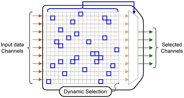
Figure 6. Block diagram of a switch matrix for channel selection.
Electrode selection has also been studied for online training of BCI algorithms. A penalized method is introduced in Moly et al. (2023) to obtain sparse decoding models when using a Recursive Exponentially Weighted N-way Partial Least Squares algorithm for training. The algorithm is based on a PARAFAC tensor decomposition (Harshman and Lundy, 1994) where the objective function to minimize is the quadratic error between the labels and predictions. With this penalized method, an additional cost term, proportional to the number of electrodes, is added to the objective function. By applying this penalization, a model with 75% sparsity was obtained, meaning that only one out of every four electrodes was required. The sparse model achieved a cosine similarity close to that of the original model, thus reducing compute time and memory consumption with no significant loss in accuracy.
Other techniques can be used for electrode selection. The authors in Wang et al. (2019) select a subset of the available electrodes that maximizes the contrast between the classified states. By applying this technique, they were able to empirically select the seven best channels out of the 32 available to be used for decoding. Other criteria can be used for channel selection. For instance, the Fisher criterion was used in Won et al. (2014) to determine the top seven channels to be used for decoding. The authors in Zhong et al. (2024) and Chamanzar et al. (2017) select the best channels as the ones achieving the highest decoding accuracy for a specific task. Finally, the selection can also be based on previous works that have determined spatial localization of task-related brain signals, such as was done in Ma et al. (2019). More precisely, in Zhong et al. (2024), only eight electrodes are selected to be placed at specific positions on a head-strap to support a variety of mental tasks. Then, a subset of these electrodes is used for each task, which minimizes the amount of input data to process, hence the power consumption.
Although less common, it is possible to combine inputs from different electrodes such as the approach in Boi et al. (2016) where data from 15 different channels is merged to create a combined spike train. This optimization makes it possible to use a reduced number of synapses per neuron in the downstream SNN (SNN) decoder.
4.1.2 Feature reduction and selectionInput selection is not limited to the raw input signals, but can also be applied for the extracted features. When we refer to feature selection, it means that certain features that were initially identified, are completely eliminated. When feature selection is applied, there is a double benefit: the eliminated features no longer need to be computed, which reduces energy, and the size of the downstream decoder is reduced. Feature reduction consists of combining the computed features into a reduced intermediate representation that is used by the decoder. However, the energy savings are limited to the decoder level as all the features are computed and then combined. Both techniques are common in the BCI literature, and they can be combined with electrode selection techniques. Figure 7 shows a diagram of a general circuit that uses a feature selection module to extract features adapted to a given task. The dynamically chosen features are then combined (projected in a latent space) using a feature reduction block.
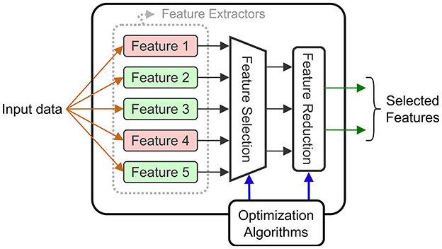
Figure 7. Block diagram of a feature extraction block supporting selection and reduction.
The authors in Wang et al. (2019) perform feature reduction using a class-wise PCA (retaining 92% of variance per class) to extract linear combinations of two selected EBs (one is in the α and β bands, the other in the high-γ band). These linear combinations are then reduced to a single value using LDA (LDA), and this value is fed to a Bayesian decoder for ECoG motor (grasp) decoding. In earlier work, the same authors (Wang et al., 2016) also implemented a similar approach on a DSP, however, the PCA was done across all the data, using a higher threshold (99.7%) for the retained variance.
The epileptic seizure detection SoC (SoC) in Chen et al. (2010) has a hardware module to extract multiple types of features, followed by a dimension reduction unit that combines the extracted features for inference. The reduction unit is programmable and could implement a PCA that has been computed offline. The feature reduction step contributes to the low-power implementation, and enables the classification using a micro-processor.
In Chamanzar et al. (2017), a different approach is used based on an adaptive WT (WT). The key idea is to generate, during the training phase, a special template that identifies the onset of movement intent. For each of the two classes, the FFT (FFT) of the input signal is calculated. Using the Fisher Discriminant Ratio, they identify a small set of frequency bands that best discriminate between the classes. The iFFT (iFFT) of these selected frequency bands is computed, thus providing a template which is used for detection. Using this approach for designing a custom filter, requires less power than extracting each of the required frequency components, which is an interesting approach for feature selection. The Fisher criterion is also used in Won et al. (2014) to select the six best frequency bands for a decoder using a DCT (DCT) to extract EB features.
Another adaptive method is applied in Malekzadeh-Arasteh et al. (2020) where the circuit extracts power envelopes in the gamma band using band-pass filters. Since the specific frequency range varies between individuals, a dual-mode architecture is proposed with two operating regimes: FB (FB) and BB (BB) modes. In the FB mode, the circuit captures the raw brain signals in the analog front-end layer with high resolution (8–10 bits sampled at 13 KHz), and the digital back-end uses these signals to compute patient specific weights, for filters in the neural pre-processing unit. For inference, the system operates in the BB mode with lower ADC resolution (3–4 bits sampled at 260 Hz). In this mode, power-band features are extracted using the previously calibrated filters.
In addition to reducing the number of features, off-chip processing can help in selecting the set of extracted features when the circuit offers a configurable feature extraction engine. As the circuit in Shin et al. (2022) is meant to be used for different applications, a set of varied features is extracted from the selected electrodes. These consist of: LL (LL), LMP (LMP), HFO (HFO), Hjorth parameters [ACT (ACT), MOB (MOB) and COM (COM)], PAC (PAC), PLV (PLV) and EB (EB) extracted using band-pass filters. The authors reduce power using an energy-aware objective function for training that minimizes cross-entropy while also penalizing the use of features requiring a high power consumption. This method reduces power by 64% while resulting in less than a 2% loss in decoding accuracy.
The circuit in Shaeri et al. (2024) extracts DNC (DNC) features to decode handwritten characters. These features correspond to spike rates at different time windows measured from different electrodes. An offline algorithm selects the 64 DNCs that best distinguish a given class, and these are fed into a LDA decoder for classification. Feature selection reduces the number of operations by a factor of 320 × and the memory size by 7.8 × .
All the feature selection and reduction methods aim to take into account an optimized set of features (often determined offline) that reduces the required compute power for inference. The optimizations can be combined with other methods to further reduce the power consumption of BCI systems.
4.2 Compute optimizationAs seen above, reducing the number of electrodes and the number of features directly reduces the number of compute operations, thus overall power. However, the power also depends on the way these operations are implemented in hardware. We review some techniques that have been used to efficiently implement specific compute operations.
4.2.1 Approximate compute operationsAnother approach to reduce power consumption is to reduce the precision of the decoding computations, often using approximate computing techniques. For example, to implement the feature extraction methods efficiently in hardware, the authors in Shin et al. (2022) approximate the theoretical definitions for the features, with simplified equations. For example, the L2-norm is replaced by L1 when computing the HPs (HPs), and the phase is computed using a linear arctangent approximation with a LUT (LUT) error correction. These simplifications yield features similar to the theoretical ones computed in Matlab (with a median correlation above 0.9) but at a lower compute cost. Similarly, the authors in Rapoport et al. (2012) use a low-power spike pattern matching based on a logical AND comparison between the spike counts instead of a costly multiplication.
The circuit in Agrawal et al. (2016) implements a simplified PCA algorithm, described in Chen et al. (2008), which uses only adders and multipliers. The norm and division operators are simplified to additions and multiplications using fixed-point arithmetic. In addition, a log-sigmoid activation function is implemented using a LUT, taking input values between –5 and 5 expressed as 9-bit values.
Moving from floating-point to fixed-point arithmetic is common in low-power decoding circuits (Shin et al., 2022; An et al., 2022; Ma et al., 2019; Sridhara et al., 2011). The circuit in Won et al. (2014) achieves a 82.9% (resp. 75.7%) accuracy when using fixed-point (resp. floating point) operations. The authors suggest that, in some cases, the quantization for fixed-point arithmetic can remove random ECoG noise, thus yielding a better decoding accuracy. In addition to using fixed-point arithmetic, the chip in Yoon et al. (2021) supports custom precision to save power. They report a “99.7% match” compared to the original approach with floating-point arithmetic.
More system-level approximations can be applied to further reduce the power consumption. For example, the circuit in Zhong et al. (2024) implements a teacher-student CNN (CNN) approach for decoding. It consists of two CNNs with different architectures: the teacher, a large model with high power consumption and high decoding accuracy, and the student, a smaller model that consumes 70% less energy, but achieves a 14% lower accuracy. During the decoding process, only the student model is turned on when the same state is decoded. The system switches between both models only when a state transition is detected with a low confidence level. This level is defined according to a confusion matrix between the decoders' outputs. The hybrid architecture reduces the overall energy consumption by 55%. The system also takes advantage of the EEG signal sparsity for further power reduction.
4.2.2 Merging operationsAnother technique to reduce the number of compute operations is to merge multiple operations in the decoding equations. In other words, certain steps can be reordered or combined before being implemented in hardware.
An interesting combination method is described in Wu et al. (2024) where SSVEP (SSVEP) are decoded using a TRCA (TRCA) algorithm. The processing combines three main steps: pre-processing using a temporal filter, feature extraction with spatial filtering, and pattern recognition with a SSVEP template signal. The steps are mapped into a single matrix for fast computation. In this paper, the decoder's updates are directly applied to the combined matrix, based on a feedback signal.
In Won et al. (2014) a DCT is applied to extract the signal energy at given frequencies. The DCT of a signal is defined by Equation 5.
Xm=∑n=0N-1xncos[mπN(n+12)] (5)Where m is a scaling parameter fixing a frequency and N the length of the input signal. To reduce the number of multiplications, the authors propose a reduced-resolution quantization of the cosine function in Equation 5. In fact, by using 11 levels of quantization ( ≤ 4 bits), the system only requires 11 multiplications to compute the DCT, regardless of the size of the input signal. More precisely, the input signal samples are divided (using a LUT based on their indexes) into 11 sets and the elements of each set are summed before multiplying with the corresponding quantized cosine coefficient. This technique can be more generally applied to any large sum of products, assuming one of the factors can be coarsely quantized.
4.3 Circuit-level optimizationsIn addition to input and compute optimizations, some circuits propose circuit-level improvements. These can include analog implementations of the compute operations or other custom low-power circuit techniques.
4.3.1 Analog approachesIn BCI systems, input signals are analog. While digital circuits offer greater flexibility and ease of design than their analog counterparts, they require multi-channel, low noise ADCs at a sampling rate ranging from a few hundreds to a few thousands of Hz to provide the digitized input data. This section examines power-saving optimizations enabled by analog integrated circuits, focusing on two types: analog feature extraction and analog-based accelerators for brain signal decoding.
A typical processing task is energy extraction over one or several frequency bands. Performing this fun
Comments (0)