
Remember me


This section briefly describes the octree-based deformation model driven by the PBD method, which is the basis of this study [11]. Then, a method is proposed for mapping octree deformation results to a high-resolution organ model on a GPU.
Overview of octree deformable modelAmong spatial partitioning methods with multiple resolutions, octree is easier to handle than other partitioning methods because it fits directly into the Cartesian coordinate system. By devising the arrangement of cubes of multiple sizes, simulations of organ model deformations can be generated with high resolution and high speed. The deformation of an organ model is generated along the following steps.
Step1:Overlay an octree model on the target organ model.
Step2:Generate the deformation of the octree model.
Step3:Map the octree deformation to the organ model vertices.
Step4:The organ model is rendered.
Step5:Repeat Steps 2 to 4.
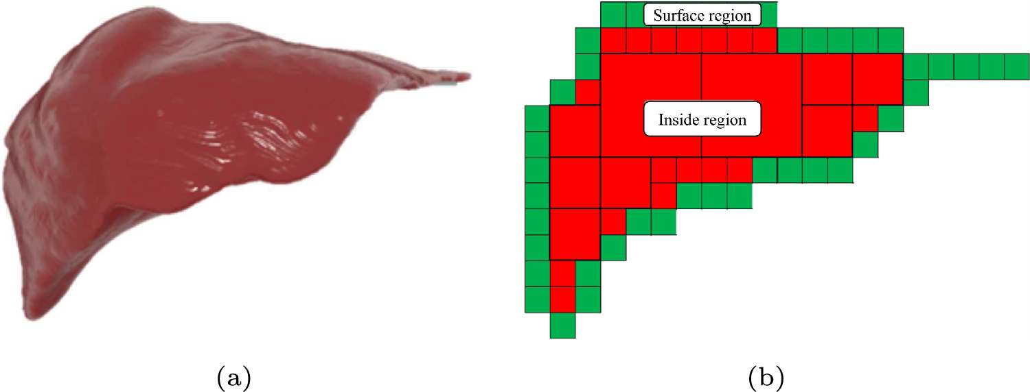
Octree cube layoutIn Step 1, an octree cube model is generated from the target organ model by method [11]. Figure 1 shows a 2D illustration of a sample of an octree cube layout. As shown in Fig. 1b, each cube is classified into two regions, inside or surface. The cubes of the surface region have vertices of the organ model, while the cubes of the inside region haven’t.
In Step 2, the motion of the octree deformation model is generated by applying the PBD method [9, 13]. This process is applied to all cubes. We use the undeformed state of each cube in the octree as a constraint for the PBD method [11].
Fig. 1
a A surface organ model and b a sample layout of cube placement. An octree model is generated from a high-resolution organ surface model. Hierarchal cubes are classified into two regions, inside or surface
Fig. 2
\(\varvec'\) is the position \(\varvec\) moved due to the deformation, which is obtained from 8-cube vertex coordinates by trilinear interpolation
Cube deformation mappingSteps 2 to 4 are performed once per video frame interval. The mapping process in Step 3 is also seen in free-form deformation (FFD), where the movement of control points is reflected in the model to be deformed. This process is done by trilinear interpolation of the 8 vertex coordinates of the cube. This means that the vertex position vector of the organ model is given as input, and the new position vector is obtained along with the deformation of the cube. This process is only performed for cubes classified as surface region, while the PBD method was applied to all cubes in Step 2. The details are described below.
Figure 2 shows that any position \(\varvec\) in the cube moves according to the deformation of the cube. \(\varvec_i\) and \(\varvec'_i\ (i=0, 1, \ldots , 7)\) are the vertices of the cube before and after deformation, respectively. \(\varvec'\) is the position of \(\varvec\) after the deformation. For trilinear interpolation, the local coordinates \(\varvec_}(x, y, z)\) of \(\varvec\) in the cube are prepared by normalizing by the length L of the cube’s edges. For correct shading, the trilinear interpolation is also applied to the normal vector of each vertex.
$$\begin \varvec_}(x, y, z) =\dfrac - \varvec_0}. \end$$
(1)
Then, the interior points \(\varvec_0\) to \(\varvec_5\) are
$$\begin \varvec_0&= x (\varvec'_1 - \varvec'_0) + \varvec'_0, \end$$
(2)
$$\begin \varvec_1&= x (\varvec'_3 - \varvec'_2) + \varvec'_2, \end$$
(3)
$$\begin \varvec_2&= x (\varvec'_5 - \varvec'_4) + \varvec'_4, \end$$
(4)
$$\begin \varvec_3&= x (\varvec'_7 - \varvec'_6) + \varvec'_6, \end$$
(5)
$$\begin \varvec_4&= y (\varvec_1-\varvec_0) + \varvec_0, \end$$
(6)
$$\begin \textrm \ \ \varvec_5&= y (\varvec_3-\varvec_2) + \varvec_2. \end$$
(7)
Finally, \(\varvec'\) is obtained as:
$$\begin \varvec' = z(\varvec_5-\varvec_4) + \varvec_4. \end$$
(8)
GPU-based trilinear interpolationIn the PBD method, the iterative process of motion generation is performed in Step 2, and the number of iterations should be as many as possible to enable real-time processing. However, the mapping process in Step 3 consumes non-negligible processing time, although it is sufficient to perform it once per video frame interval. For example, 16 treads of parallel processing on an AMD Ryzen 3700X, Step 3, take 13 ms for a liver model consisting of approximately 257,000 vertices, which is about 40% of the 33-ms frame interval time at 30 fps. Therefore, we attempt to execute the trilinear interpolation of Step 3 on the GPU. Figure 3 compares the CPU and GPU implementations of the trilinear interpolation process.
Fig. 3
Difference of implementation of trilinear interpolation between CPU and GPU
In the Unity, the current standard platform for surgical simulation development, a single organ model is treated as a single object, called GameObject. For CPU-based processing, trilinear interpolation is written in a single C# script, allowing easy access to both the vertices of the cube and the organ model.
However, to achieve this with GPU shader processing, the organ model cannot be processed as a single GameObject because the cube vertex coordinates required for trilinear interpolation vary depending on the cube containing each vertex of the organ model. Therefore, the entire organ model is split into multiple objects according to the octree cube arrangement so that a portion of the organ model fits into a single cube, and the 8-cube vertex coordinates used for trilinear interpolation are unique for a single GameObject. Each GameObject has a C#script attached to it to pass the cube vertex coordinates to the vertex shader. The coordinate values of the vertices that are poured into the vertex shader are not absolute 3D positions, but normalized local coordinates in the cube defined by Eq. (1). Within the rendering process, trilinear interpolation is applied to the arriving vertices by the vertex shader process and passed to the fragment shader, the next process in rendering.
Comments (0)